


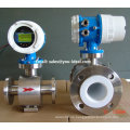
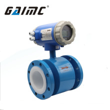
Feld Anzeige Wasser / Flüssigkeit / Kraftstoff Turbine Durchflussmesser
Basisinformation
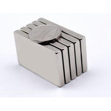
Modell: LWGY
Produktbeschreibung
Modell Nr .: LWGY Hauptanwendung: Wasser, Diesel Treibstoff, Treibstoff Öl, Natur Gas, Korrosive Flüssigkeit / Gas Sensor: Rohr / Flansch Typ: Turbine Durchflussmesser Messprinzip: Atom Physik Zertifizierung: JIS, DIN, ANS, GB, CE, UL, RoHS, ISO Druck: Geeignet für sehr hohen Druck LCD: Ja / Nein Warenzeichen: U-ideal Spezifikation: ISO HS Code: 90261000 Genauigkeit: ± 0,2-0,5% Größe: Dn10-Dn250 Anwendung: Industrielle Fertigung Messmedien: Flüssig oder Gasmessung Objekt: Geschlossene Pipeline Medium: Liquid, Air, Gas Signal: Pulse, 4 ~ 20mA, Hart, RS485 Ex-Proof: Eigensicherheit / Explosionsgeschützte Transport Verpackung: Holzkoffer oder Karton Herkunft: Tianjin, China Competitive 4 ~ 20mA Und Feldanzeige WASSER Turbine Durchflussmesser, Durchflussmesser
Kann für Maßvolumenstrom von Flüssigkeit oder Luft verwendet werden, zB Luftstrommessung, Wasserdurchflussprüfung, Dieselöl-Durchflussmesser.
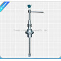
1. Funktionsprinzip:
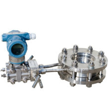
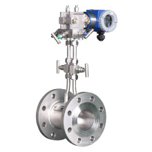
Flüssigkeit fließt durch das Turbinengehäuse, wodurch ein Innenrotor sich dreht. Wenn sich der Rotor dreht, wird ein elektrisches Signal in der Aufnahmespule erzeugt. Dieses Signal wird in den technischen Einheiten (Liter, Kubikmeter, Gallonen etc.) auf dem lokalen Display umgewandelt, wo anwendbar ist. Mit optionalen Zubehörmodulen können Sie das Signal auf andere Geräte exportieren.
Nach Erhalt prüfen Sie Ihr Messgerät auf sichtbare Schäden. Die Turbine ist ein Präzisionsmessgerät und sollte sorgfältig gehandhabt werden. Entfernen Sie die Schutzstecker und die Kappen für eine gründliche Inspektion. Wenn irgendwelche Gegenstände beschädigt oder fehlen, wenden Sie sich an U-IDEAL.
Stellen Sie sicher, dass das Turbinenströmungsmodell Ihren spezifischen Bedürfnissen entspricht. Für Ihre zukünftige Referenz kann es sinnvoll sein, diese Informationen auf dem Typenschild im Handbuch aufzuzeichnen, falls es auf der Turbine unlesbar wird. Beziehen Sie sich auf das Typenschild für die Spezifikation Ihres kundenspezifischen Produkts. 2. Technische Daten
Messsystem
Entwurf
Messgenauigkeit
Betriebsbedingungen
Einbaubedingungen
Materialien
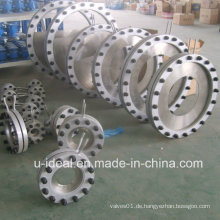
Prozessanschlüsse
Messbarer Durchflussbereich:
Hinweis: Der Durchflussbereich als Blow dient nur als Referenz. Wenden Sie sich an die Fabrik, wenn Sie besondere Anforderung haben. Beziehen Sie sich auf das Typenschild oder das Zertifikat für den tatsächlichen Durchflussbereich.
3. Modell- und Auswahlmodellauswahl (siehe Tabelle 1)
Tabelle 1: Modellauswahl für Flüssig-Turbinen-Durchflussmesser
Modellcode: LWGY-050C10SSNN-A1-T1
Erläuterung - Durchmesser: 50mm; Konverter: 24V DC Stromversorgung, 4-20mA Ausgang, Lokale Anzeige
Genauigkeit: 1,0%; Durchflussbereich: 4-40 m3 / h; Körper-Material: SS304; Keine Explosion; Anschluss: ANSI 150 # Flansch; Flüssigkeitstemperatur: -20 ... + 80 ° C
Kann für Maßvolumenstrom von Flüssigkeit oder Luft verwendet werden, zB Luftstrommessung, Wasserdurchflussprüfung, Dieselöl-Durchflussmesser.
1. Funktionsprinzip:
Flüssigkeit fließt durch das Turbinengehäuse, wodurch ein Innenrotor sich dreht. Wenn sich der Rotor dreht, wird ein elektrisches Signal in der Aufnahmespule erzeugt. Dieses Signal wird in den technischen Einheiten (Liter, Kubikmeter, Gallonen etc.) auf dem lokalen Display umgewandelt, wo anwendbar ist. Mit optionalen Zubehörmodulen können Sie das Signal auf andere Geräte exportieren.
Nach Erhalt prüfen Sie Ihr Messgerät auf sichtbare Schäden. Die Turbine ist ein Präzisionsmessgerät und sollte sorgfältig gehandhabt werden. Entfernen Sie die Schutzstecker und die Kappen für eine gründliche Inspektion. Wenn irgendwelche Gegenstände beschädigt oder fehlen, wenden Sie sich an U-IDEAL.
Stellen Sie sicher, dass das Turbinenströmungsmodell Ihren spezifischen Bedürfnissen entspricht. Für Ihre zukünftige Referenz kann es sinnvoll sein, diese Informationen auf dem Typenschild im Handbuch aufzuzeichnen, falls es auf der Turbine unlesbar wird. Beziehen Sie sich auf das Typenschild für die Spezifikation Ihres kundenspezifischen Produkts. 2. Technische Daten
Messsystem
| Application range |
Liquid: water; diesel; gasoline
|
| Measured Value | |
| Primary measured value | Flow Rate |
| Secondary measured value | Volume flow |
Entwurf
| Features | |
| Modular construction | The measurement system consists of a flow sensor and a signal converter. It is available as compact and as separate version. |
|
Compact version converter |
N Type: Pulse output without local display |
| A Type: 4-20mA Output without local display | |
|
B Type: Local Display; Lithium Battery Power; No Output | |
|
C Type: Local Display; 24V DC Power; 4-20mA Output; Optional Function:
| |
|
Connection |
Thread: DN4-DN50 |
| Flange: DN15-DN200 (DIN, ANSI, JIS) | |
| Wafer: DN15-DN100 | |
| Measurement Ratio | Standard - 10:1; Optional: 20:1 |
Messgenauigkeit
| Reference conditions | Flow conditions similar to EN 29104 |
| Medium: Water | |
| Electrical conductivity: ≥ 300 μS/cm | |
| Temperature: +10...+30°C / +50...+86°F | |
| Inlet section: ≥ 10 DN | |
| Operating pressure: 1 bar / 14.5 psig | |
|
Flow Meter Accuracy |
Standard: 1.0% of rate |
| Optional: 0.5% of rate |
Betriebsbedingungen
| Temperature | |
| Process temperature | T1 Level: -20...+80°C |
| T2 Level: -20...+120°C | |
| T3 Level: -20...+150°C | |
|
Ambient temperature (all versions) |
Standard (with aluminum converter housing): |
| -10…+55°C | |
| Storage temperature | -20...+70° |
| Pressure | |
| EN 1092-1 | DN100…DN200: PN 16 |
| DN15…DN80: PN 25 | |
| Other pressures on request | |
| ASME B16.5 | 1/2"...8": 150 lb RF |
| Other pressures on request | |
| JIS | 1/2"...8": 10 K |
| Other pressures on request |
Einbaubedingungen
|
Installation |
Take care that flow sensor is always fully filled |
| For detailed information see chapter "Cautions for Installation" | |
|
Flow direction |
Forward |
| Arrow on flow sensor indicates flow direction. | |
| Inlet run | ≥ 10 DN |
| Outlet run | ≥ 5 DN |
Materialien
| Sensor housing | SS304 | |
| Other materials on request | ||
|
Flanges |
SS304 | |
| Other materials on request | ||
| Rotor | ||
| Standard: 2Cr13 | EN10088-3 1.4021 | X20Cr13 |
| AISI 420 | ||
| BS 420S37 | ||
| JIS SUS410J1 | ||
| Optional: CD4MCu | DN15…DN80 | |
| Bearings and Shaft | Tungsten Carbide | |
| Converter Housing | Standard: polyurethane coated die-cast aluminum | |
Prozessanschlüsse
| Flange | |
| EN 1092-1 | DN15...200 in PN 6...40 |
| ASME | 1/2"…8" in 150 lb RF |
| JIS | 1/2"…8" in 10...20K |
| Design of gasket surface | RF |
| Other sizes or pressure ratings on request | |
| Thread | DN4…DN50 in PN63 |
Messbarer Durchflussbereich:
Hinweis: Der Durchflussbereich als Blow dient nur als Referenz. Wenden Sie sich an die Fabrik, wenn Sie besondere Anforderung haben. Beziehen Sie sich auf das Typenschild oder das Zertifikat für den tatsächlichen Durchflussbereich.
| Nominal Diameter | Standard Flow Range | Extended Flow Range | |
| (mm) | (in.) | (m3/h) | (m3/h) |
| 4 | 0.15 | 0.04 to 0.25 | 0.04 to 0.4 |
| 6 | 0.25 | 0.1 to 0.6 | 0.06 to 0.6 |
| 10 | 0.4 | 0.2 to 1.2 | 0.15 to 1.5 |
| 15 | 0.5 | 0.6 to 6 | 0.4 to 8 |
| 20 | 0.75 | 0.8 to 8 | 0.45 to 9 |
| 25 | 1 | 1 to 10 | 0.5 to 10 |
| 32 | 1.25 | 1.5 to 15 | 0.8 to 15 |
| 40 | 1.5 | 2 to 20 | 1 to 20 |
| 50 | 2 | 4 to 40 | 2 to 40 |
| 65 | 2.5 | 7 to 70 | 4 to 70 |
| 80 | 3 | 10 to 100 | 5 to 100 |
| 100 | 4 | 20 to 200 | 10 to 200 |
| 125 | 5 | 25 to 250 | 13 to 250 |
| 150 | 6 | 30 to 300 | 15 to 300 |
| 200 | 8 | 80 to 800 | 40 to 800 |
Tabelle 1: Modellauswahl für Flüssig-Turbinen-Durchflussmesser
| Model Suffix Code | Description | |||||||||
| LWGY- | ||||||||||
| Diameter |
Three Digitals; for example: 010: 10 mm; 015: 15 mm; 080: 80 mm; 100: 100 mm |
|||||||||
| Converter | N | No display; 24V DC; Pulse Output | ||||||||
| A | No display; 24V DC; 4-20mA Output | |||||||||
| B | Local display; Lithium Battery Power; No output | |||||||||
| C |
Local display; 24V DC Power; 4-20mA Output; Optional backup power: Lithium Battery |
|||||||||
| C1 |
Local display; 24V DC Power; 4-20mA Output; Modbus RS485 Communication Optional backup power: Lithium Battery |
|||||||||
| H |
Local display; 24V DC Power; 4-wire 4-20mA Output & HART Communication |
|||||||||
| Accuracy | ||||||||||
| 05 | 0.5% of Rate | |||||||||
| Flow Range | S | Standard Range: refer to flow range table | ||||||||
| W | Wide Range: refer to flow range table | |||||||||
| Body Material | S | SS304 | ||||||||
| L | SS316 | |||||||||
| Explosion Rating | N | Safety Field without Explosion | ||||||||
| E | ExdIIBT6 | |||||||||
| Pressuring Rating | N | Standard | ||||||||
| H(x) | Customized Pressure Rating | |||||||||
| Connection | -DXX |
DXX: D06, D10, D16, D25, D40 D06: DIN PN6; D10: DIN PN10 D16: DIN PN16; D25: DIN PN25 D40: DIN PN40 |
||||||||
| -AX |
AX: A1, A3, A6 A1: ANSI 150#; A3: ANSI 300# A6: ANSI 600# |
|||||||||
| -JX |
JX: J1, J2, J4 J1: JIS 10K; J2: JIS 20K; J4: JIS 40K |
|||||||||
| -TH | Thread; DN4…DN50 | |||||||||
| Fluid Temperature | -T1 | -20...+80°C | ||||||||
| -T2 | -20...+120°C | |||||||||
| -T3 | -20...+150°C | |||||||||
Erläuterung - Durchmesser: 50mm; Konverter: 24V DC Stromversorgung, 4-20mA Ausgang, Lokale Anzeige
Genauigkeit: 1,0%; Durchflussbereich: 4-40 m3 / h; Körper-Material: SS304; Keine Explosion; Anschluss: ANSI 150 # Flansch; Flüssigkeitstemperatur: -20 ... + 80 ° C
Produktgruppe : Durchflussmesser > Andere Durchflussmesser
Premium Related Products


andere Produkte
heiße Produkte
Hochdruck-Erdgas-Instrument LuftverteilerEdelstahl-Industrie-3-Wege-VentilverteilerSchwimmerwinkel Doppelblock und Entlüftungsventil3-fach abschließbarer geschlitzter KugelhahnEdelstahl-Dreiwege-KugelhahnGewinde-Edelstahl-KugelhähneRostfreies Hochdruckluft-Präzisions-NadelventilRohr-Kompressionsverschraubungen Winkel Luft betreiben NadelventilCf8m Edelstahl weiblichen männlichen automatischen Kugelhahn.JW-LOK Hamlet Instrument KugelhahnEdelstahl-Mehrfach-Manometer-VentilHochdruck-2-Wege-VentilverteilerHochdruck 6000psig bar Lager KugelhahnSpeedy Zapfen Kugelhahn für ErdgasDie meisten verkaufenden Produkte des Kühler-SelbstentlüftungsventilsHochwertiges geschmiedetes Stahlkolbenkugelventil